
the Woomera Range in 1960
the Woomera Range in 1960
from "ELDO IN AUSTRALIA "April 1966 prepared by Weapons Research Establishment on behalf of the ELDO
THE WOOMERA RANGE (1960)
The Woomera Range is the main trials area of the Weapons Research Establishment Salisbury, S. A. which in turn is controlled by the Commonwealth Department of Supply. The Range is a multi-purppse one, handling large vehicles such as the EUROPA I and Black Knight as well as sounding rockets and military weapons. Missiles at the Range are prepared for firing by various government authorities, private firms or groups of nations such as ELDO. The management of the Range and the provision and operation of Range facilities including Range instrumentation is the function of SURE.
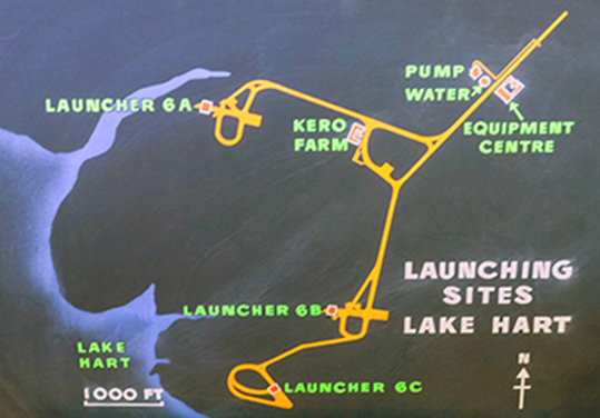
The ELDO launch complex at Area 6 is one of several launchers positioned around the Rangehead at Range E. Safety considerations, and the topographical advantages of the gullies on the Lake Hart shoreline determined the positioning of Area 6. Control of checkout activities at Area 6 before launch is generally from the E.C. 6 Control Room but once airborne the vehicle is tracked and monitored by the Range instrumentation system. The ELDO Down Range Guidance and Tracking Station at Gove in the Northern Territory, will be linked into this system and will track and control the 3rd Stage vehicle as it is positioned for in-serting the satellite into orbit.
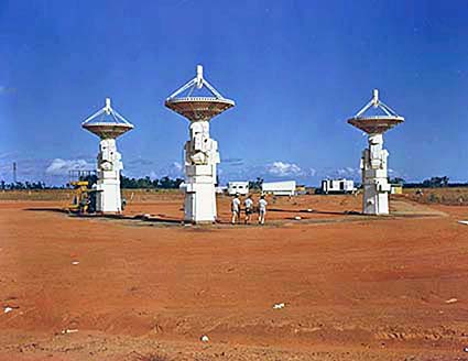
tracking station at Gove
ELDO LAUNCH COMPLEX
The various ELDO member states have, or will have special support equipment in one of the several areas of the launch complex. These areas are :
1. Preparation Area
2. Equipment Centre N° 6 and Pump House Area
3, Common Services Area
4. Launcher 6A Area
Other facilities on the site include launcher 6B, but this area was left unfinished after the cancellation of the Blue Streak weapon project in 1960 and is not at present part of the ELDO operational complex.
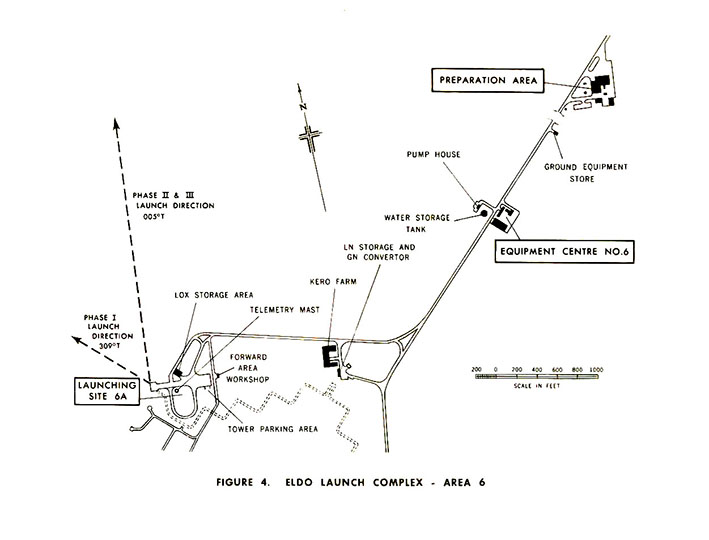
Figure 4 shows the complete launch complex in plan.
Preparation Area
The Preparation Area is used to prepare the launch vehicle and satellite for flight before the final checkout on the launcher proper, and has office, workshop, and stores facilities. It is located 21 miles from the launcher itself and is thus protected should a vehicle loaded with propellants explode on the launcher or at lift off.
Equipment Centre N°6
The Equipment Centre, situated II miles from the Preparation Area and about 4 000ft from the launcher, houses most of the remote control and monitoring equipment for the vehicle and site systems.
During the final part of a launch countdown sequence, the Control Roots is the nearest manned position to the launcher, accommodating up to 75 people. Because of this it is specially strengthened against blast and flying debris if a catastrophic failure occurs at launch.
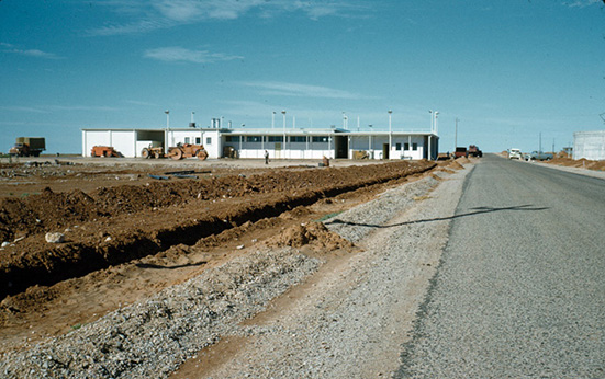

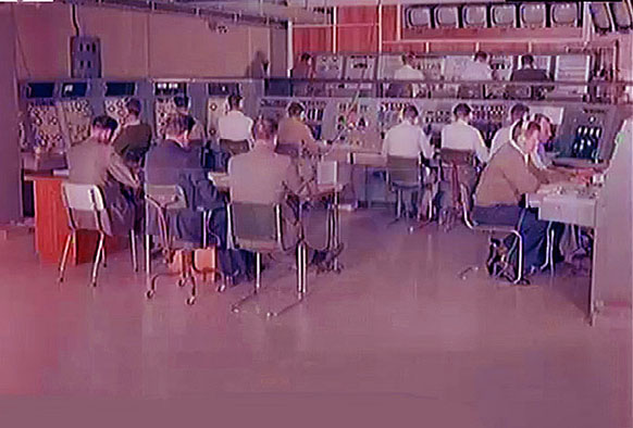
Figure shows part of the control Room during the last few minutes of a launch countdown.
Pump House
Facing the Equipment Centre on the other side of the road, is a circular concrete water tank with a capacity of 300 000 gallons. Behind the tank is the water pump house, which contains firefighting and domestic water pumps, control valves, and monitoring equipment.
Flow rates of up to 4 000 gallons/minute are available and services can be remotely controlled to combat fires which may start in the vehicle or on the launcher.
pump house
Common Services Area
Between the Equipment Centre and the Launcher are the kerosene storage tanks: a tank for the storage of liquid nitrogen and facilities for conversion of liquid nitrogen into its gaseous form. This is the Common Services Area.
The gaseous nitrogen is reticulated to vehicle and launcher systems for pressurisation of liquid storage tanks, actuation of remotely operated valves, and purging of vehicle engine systems.
liquid oxygen tanks
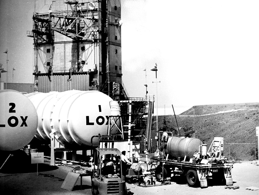
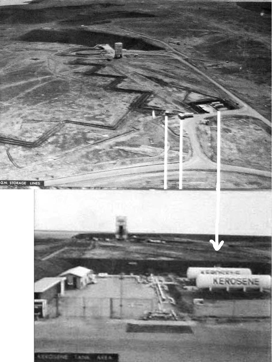
kerosene storage tanks area
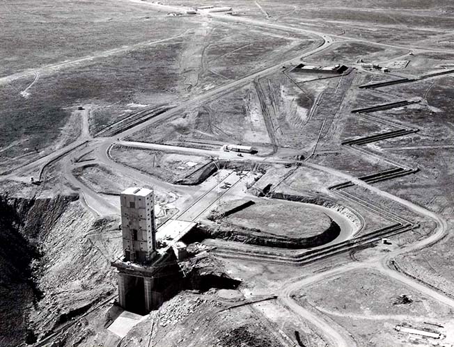

figure 111
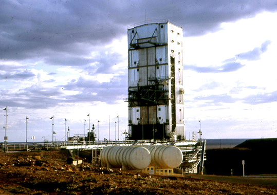
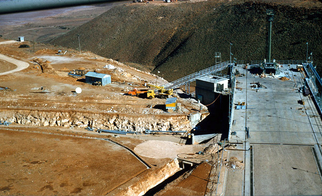
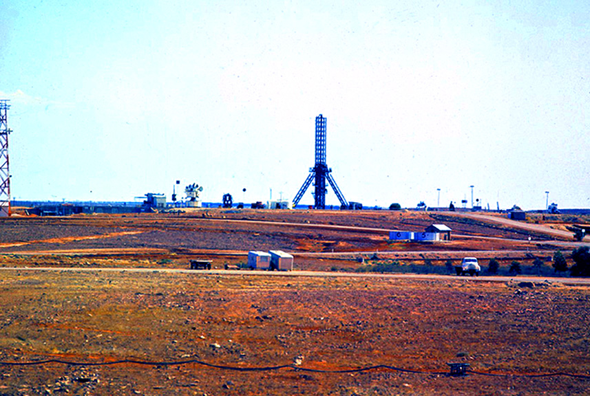
The launcher Area
The Launcher, shown in Figure 6, has been built near a natural gully to take advantage of the additional height this afforded for the escape of the 1st Stage engine exhaust flame into the efflux duct. The duct is hid with het resistant tiles, and the difficulties of water cooling in an arid area are thus avoided.
At the western end of the launcher emplacement is the launcher assembly on which the vehicle stands. All ground supplies connected to the vehicle terminate on this assembly or the adjacent umbilical mast.
The umbilical mast, 120ft high, carries electrical, liquid, and gas connections to the 2nd and 3rd Stage rockets and the satellite. The 1st Stage electrical and cooling air supplies are carried by the tubular section nearer to the launcher.
The 500 ton mobile Service Tower is 130ft high and has 10 servicing levels to provide access to each stage of the vehicle. Lifting facilities are provided by several cranes. The Tower is removed from around the vehicle shortly before launch. It travels to the other end of the launcher at a speed of 30 ft/minute, under electrical power supplied by storage batteries in the top of the tower.
Under the emplacement Is the Test Post. This is a forward checkout area which is used during the pre-launch preparation phase to prove many vehicle and site systerns. Also located around the Test Post are control and distribution equipment for gaseous nitrogen, d. ti. power, air conditioning and other services.

THE ELDO LAUNCH PREPARATION AND COUNTDOWN
There are three distinct steps which must follow the arrival of each Stage at the ELDO launch complex before a launch can occur.
They are
1. Checkout of each vehicle stage by the appropriate stage teams to satisfy their specifications;
2. checkout of the complete vehicle to satisfy ELDO specifications ;
3. the final "countdown" including fuelling and arming the vehicle for flight. Safety aspects are monitored by the 'Range Authority' in accordance with standard procedures.
An extract from a proposed checkout programme is shown in Figure 7, individual checks inosing towards the ultimate proof of launch. The Countdown is conducted over a three day period and requires extensive coordination of tasks, systems readiness, safety control and logistics. A master document guides the Overall Team Leader, who is the ELDO officer in charge of Area 6 countdown operations, in executing the final checks to a pre-determined time scale. Weather, working hours and other Range commitments limit the period during which a launch may be attempted.
The last five minutes of the countdown before lift-off is conducted automati-cally by a sequencer system, control of which is vested in the main Trials Control Centre at the Rangehead.
Figure 8 shows the planned and achieved results of a 1st Stage launch count-down for vehicle F.2.

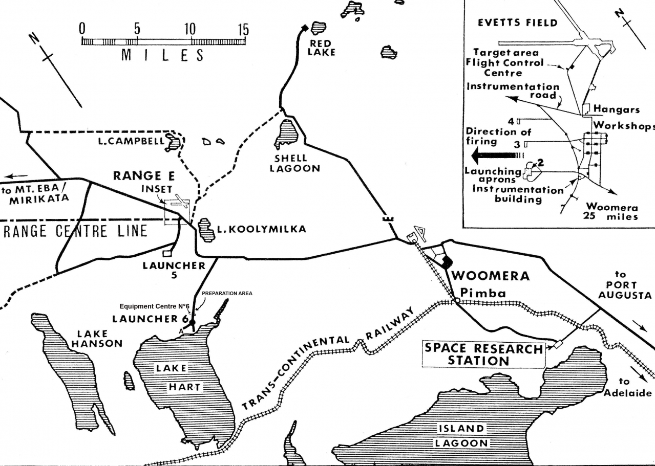
map of the Woomera range in 1960
The Rangehead
(from Space Science and Technology volume 7 Frederik I. Ordway 1965)
The rangehead (31° 58' S 136° 31' E., elevation 500 ft) is located 28 mi northwest of the town of Woomera, South Australia (Fig. 107). Including the sparsely inhabited flyover area between the rangehead and impact area at Talgarno, the range encompasses some 762,500 mil, which makes it the largest inland rocket range in the free world. The rangehead is on the southeastern edge of the Great Victoria Desert, while an as yet unused impact area on the northwestern coast of Australia lies within the Great Sandy Desert. In between is a 250-mi wide flyover strip that crosses the Musgrave Range and Gibson Desert.
The rangehead is situated on an open, rolling plain in what is called the gibber country, gibber being a local name for dry, clay soil covered with small, wind eroded stones. There is some bush cover and an occasional cane swamp. Some 40 mi from the rangehead the soil becomes red, sandy loam with broken sand hills similar to the "boon docks" of White Sands Missile Range in New Mexico. This area has some vegetation in the form of mulga trees and salt bush, and there are many dry lakes that fill but quickly evaporate after heavy rains. The whole area is homesteaded by sheep ranchers, but the homesteads are at least 40-50 mi apart, with the area having a density of no more than one man and five sheep per square mile. The maximum summer temperatures at Woomera vary between 85°F and 105°F with occasional maxima to 115°F. January is usually the hottest month. The minimum temperatures in summer range between 55°F and 72°F, with a very low humidity. Winter maximum temperatures vary between 55°F and 70°F, with occasional lows of 50°F. Minimum winter temperatures range between 35°F and 47°F, with an occasional minima of 27°F. Rainfall averages 7 in. annually, with the wettest months being January and February [65]. Since the area has at least 3,300 hr of sunshine per year, both optical and electronic tracking means operate optimally. The prevailing ground winds are from the south, southeast, and south-west. Some 43 per cent of the wind speeds range between 6 and 15 knots, while 19 per cent range between 16 and 25 knots. Strong westerly winds prevail in the upper levels of the atmosphere throughout the year, except for the summer, when they are more variable both in direction and speed.
LAUNCHING FACILITIES

Figure 106
As shown on Fig. 106, there are four launching pads at Range E (two are at the Skylark pad) and two additional launching sites to the southwest. These pads are located 600 yd apart for safety purposes, a separation permitting the simultaneous handling of explosives on the several pads. All pads are lighted for night operations. The range center-line is on an azimuth of 304° 54' 47". The Skylark launching pad and its associated facilities are shown in Fig. 108. The launcher is an open-truss structure of Bailey Bridge panels and weighs 30 tons. The launcher proper is composed of three parallel rails 100 ft long supprted near its midpoint by a gimbal frame mounted on a tripod. This gimbal permits the launcher to be moved from +15 deg to —5 deg in elevation and turn through 10 deg of traverse in azimuth. Remotely controlled electric motors drive the mechanism. The three parallel rails are adjustable so that other rockets, such as Aerobee, can also be fired from the launcher. An electric hoist on the working platform of the tower is used to lift the nosecone up to that level, while the rocket itself is brought up to the tower on a special dolly. This dolly is hinged to the base of the launching rail and then hoisted vertically, permitting the rocket to fit into the rails. Once the rocket is secured, the nosecone is fitted between the rails and mated with the rocket. External power is supplied to the rocket through umbilical plugs and cables on the launcher. At lift off these connections are ejected by pneumatic means. A ground-level Wind measuring set is attached to a mast mounted on top of the launching tower [66]. The blockhouse, or equipment center as it is called at Woomera, is located 500 ft from the base of the launcher. Positioning of the launcher, monitoring the rocket during countdown and flight, range safety, and other activities are located here. The periscope projecting from the blockhouse can be seen to the left of the tower in Fig. 108. The blockhouse for the other half of the pad is the black topped area to the right rear of the Skylark launcher. This pad contains a remotely controlled, zero length launcher for multistage reasearch and test vehicles and launchers for sounding rockets. Launchers to the left of the Skylark are used for military missiles such as Sea Slug, Thunderbird, and Bloodhound. At pads 5A and 5B, the Black Knight launching area, about 3 mi south of the Instrumentation Building at Range E, there are two launchers, each with its own rail mounted gantry and service structure, as shown in Fig. 109. The launcher is a simple arrangement of support arms that hold the rocket down until sufficient thrust is built up to insure a launch. Once this point is reached, the arms pivot backwards. Exhausts from the rocket are deflected by a water-cooled flame deflector located beneath the launch pad. An umbilical mast adjacent to the launcher supplies external power and freon gas to the rocket, the gas being used for cooling purposes. At launch quick-disconnect plugs operate and the cables fall into a net mounted on the mast. The mast is rigid and does not pivot away from the launcher during the firing sequence. Operations at both launchers are controlled from a blockhouse or equipment center located 200 yd uprange of the launchers and partially underground with an earth barricade, as shown in Fig. 110. The blockhouse contains the automatic programmer [67], control consoles, and guidance systems. Guidance of the Black Knight above 20,000 ft is from within the blockhouse by an SCR584 radar transmitter antenna mounted on the roof. Command guidance during the early, vertical phase of flight is by two M2 optical tracking devices located to the left and the rear of the launcher. The service structure of the Black Knight is used primarily to trans-port the rocket to the launcher and erect it. Hinged platforms within
the tower give working access to various levels on the rocket, and a hoist on top is used to lift the nosecone for assembly to the rocket body.
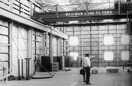
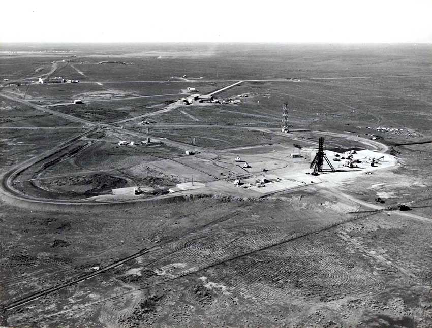
Located on top of a 200-ft escarpment at Lake Hart, a dry salt pan some 10 mi south of the rangehead, are Blue Streak launching pads, 6A and 6B. These pads are practically the same as the Blue Streak static test stand at Spadeadam, England, . The main features of pad 6A, shown in Fig. 111, are the 70-ton launcher and umbilical mast at one end of the concrete apron and the service structure at the other end [68]. Not shown is a recently constructed first stage handling building. A similar site, 6B, is located nearby. The launcher consists of two main boxed beams connected by a lighter V-gate structure with four retractable missile release clamps mounted on the main beams. The complete launcher rests on four bogies that run on rails embedded in the concrete pad. Four bolts clamp the launcher to these rails to fix it in azimuth and to prevent its rising at missile launch. The retractable release clamps are spring-loaded, hydraulically damped, and profiled to fit the missile hold-down pins. When the first stage reaches the requisite thrust, the hydraulic power is removed from the damping mechanism and the springs permit the clamps to retract. Located adjacent to the launcher on the 90-ft2 pad is an umbilical tower that remains fixed during launching rather than pivoting back from the missile. Directly beneath the launcher, in a 100-ft flame exit scoop, is an inclined flame deflector of refractory brick .

Instrumentation building in the sixties
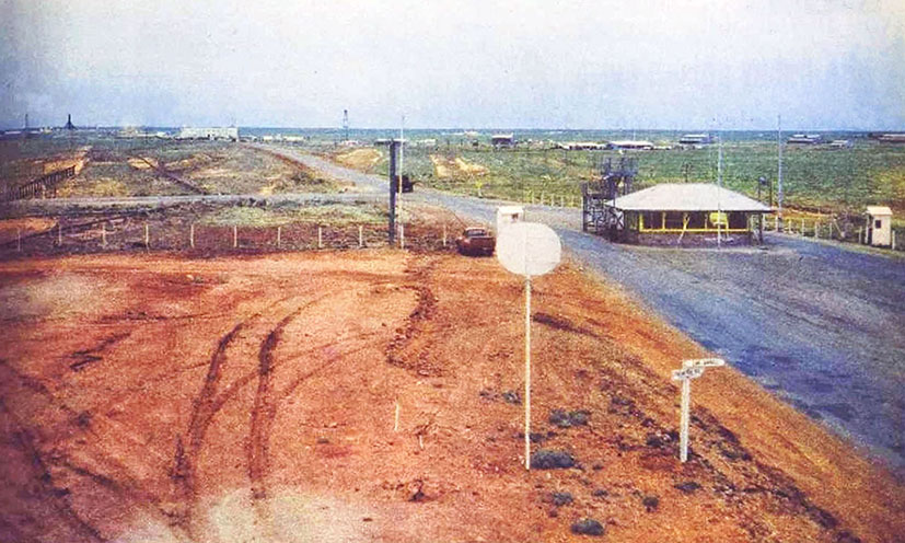
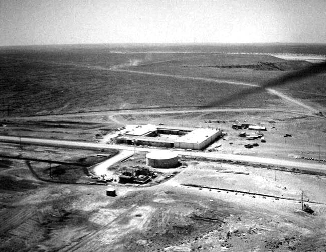
Rangehead 1962
Skylark launching pad and launcher at Woomera (courtesy Weapons Research Establishment)

the prominent Skylark launcher in the foreground) with Seaslug and Long Tom launchers respectively to the right and left of this launcher.
Behind these are the test shops and instrumentation building and in the distance a dry Lake Koolymilka